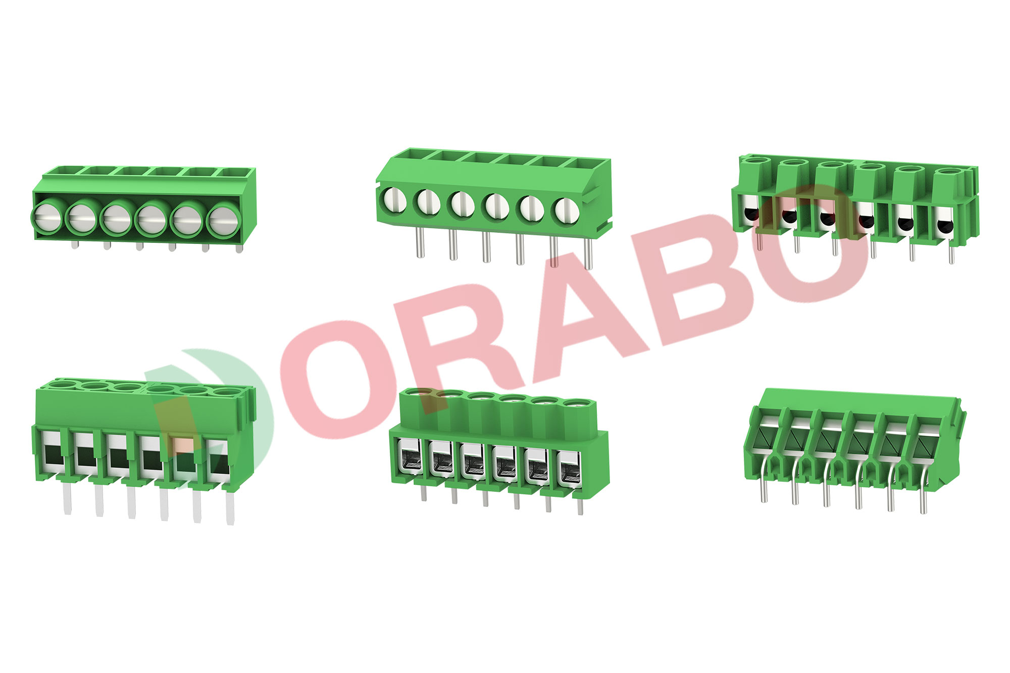
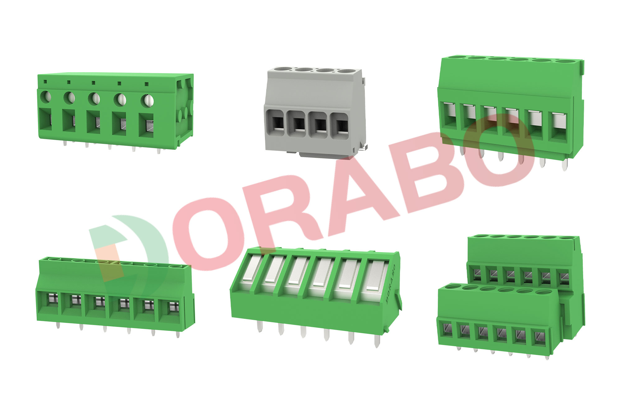
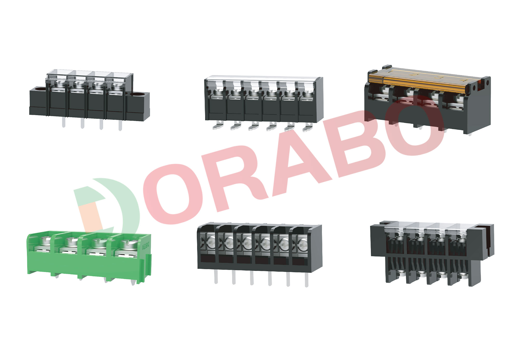
Choosing a terminal block is a simple, step-by-step process, and depends mostly on its application use case. You will need to consider such details as termination type, contact specs, orientation, mounting, and special features. The best practice method is to follow these four steps:
STEP 1: SELECT THE TYPE
We have already looked at some types of Electrical Terminal Blocks that are available. Now you will need to determine what type is required for your designated system, e.g. screw-mounted or screw-less, single feed-through or multi-level, fuse holder, ground circuit, direct mount, or disconnect.
STEP 2: DETERMINE THE ELECTRICAL SPECIFICATIONS
Next, you should determine the electrical specifications required for each terminal block, which will include maximum wire size, voltage, and current. Wire entry sizes are usually quoted in mm² and determined by their amperage ratings. The size also depends on whether the conductor being used is solid or stranded, and also what range of conductor sizes may be included during field wiring.
STEP 3: SELECT THE ACCESSORIES
Once you have chosen between a deep or shallow block housing, then you can add the appropriate end brackets and block cover(s). You may also wish to use angled support brackets, top covers, separators, internal jumpers, test plugs, and printed or blank marking tags.
Terminal blocks may also include one or more special features, such as circuit breakers, indicator lights. and lamp testing diodes. Pluggable terminal blocks are typically DIN rail mounted and can be stacked together to save space. Such blocks combine the terminals in a way that allows the power to be disconnected from the whole stack by removing one single plug.
STEP 4: CALCULATE THE RAIL LENGTH
To determine the length of DIN rail you will need in your assembly, you must calculate the total density per foot of all the different types of the terminal block and their respective quantities. Half an inch (½") must then be added for each rail end to accommodate the required rail mounting screws, plus 0.0008” (0.2 mm) additional tolerance per terminal. For the calculation to be complete, you must also add the width of the end covers, the end brackets, and any separators.


 Contact us
 Language


