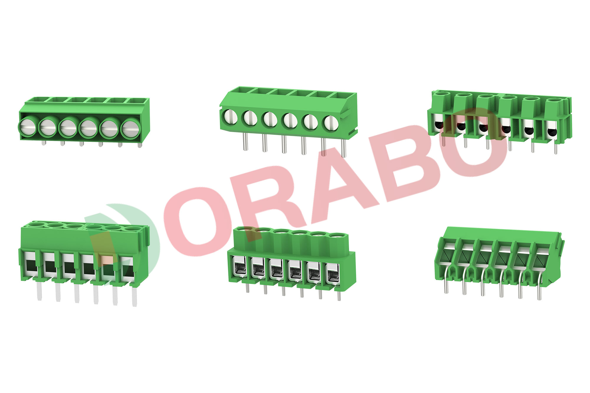
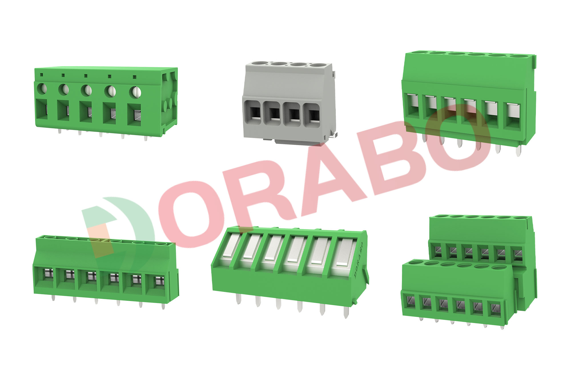
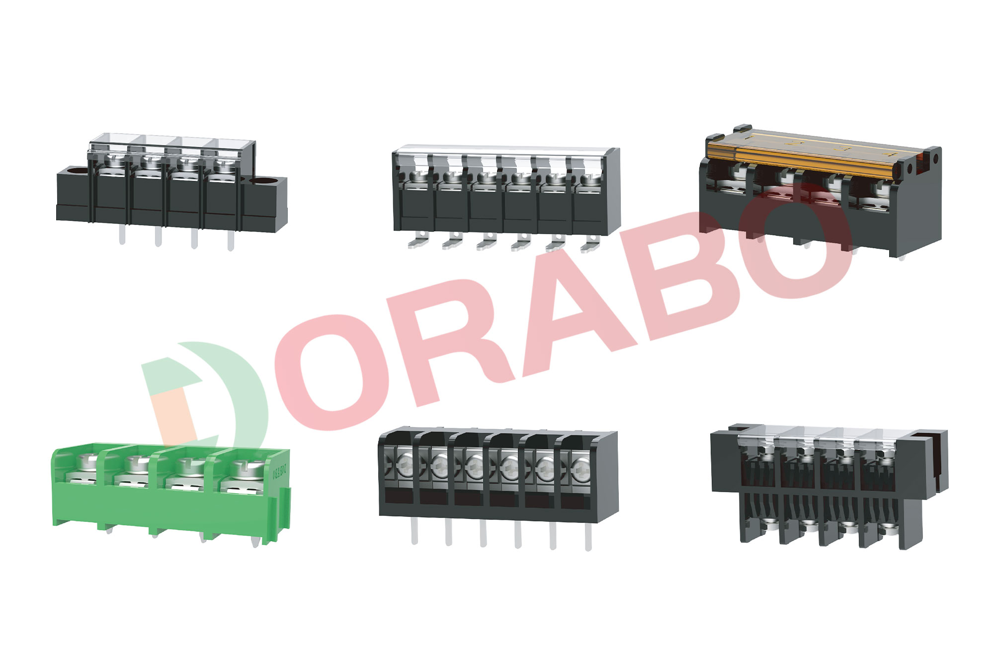
Terminal blocks consist of modular housings and insulators used to hold two or more wires together in electrical systems that require secure connections. Terminal blocks, also known as screw terminals, terminal connectors, or connection terminals, provide engineers with semi-permanent wire connections that provide organized and simplified inspection or repair capabilities in the field.
Although components are widely used in numerous applications, it is still important to have a basic understanding of common terminal block types and sizes before making a final selection. Topics that will be covered in this article include key electrical and mechanical considerations, safety ratings, and more detailed information to assist engineers in the selection process.
The three most common types of terminal blocks used in designs are PCB mounts, spacers, and feed-throughs. PCB mount terminal blocks operate by inserting bare wires into the module, where clips hold the wires in the housing. This housing is then soldered to the PCB, which is why they are often referred to as wire-to-board terminals. Also known as Eurostyle terminal blocks, they can be found in single-row, double-row, or multi-row configurations.
Where vibration is a factor, barrier strips are often used. They have a screw-in terminal that accepts bare wire or wires with rings or spades attached to the end. Simply place the wires on the screws and tighten them into the housing for a secure connection. Barrier strips are also available in a variety of configurations, including single or double rows.
Finally, the feedthrough terminal block for wire-to-wire connections contains an input and an output contact, with two separate wires plugged into opposite sides of the housing to connect the two wires together. Feed-through terminal blocks, similar to the PCB mount type, are available for single-row, dual-row or multi-row modules.


 Contact us
 Language


